IO-Link (less commonly IOLink or IO Link) is a standardized digital communication system for automation technology. The technology is described in IEC 61131-9 and connects sensors and actuators to higher-level control systems. Unlike traditional binary or analog interfaces, IO-Link enables bidirectional communication: process values, diagnostic data, and device parameters can not only be transmitted but also specifically read or changed.
Content
One significant advantage is that IO-Link does not require special fieldbus cabling. Communication occurs via simple, unshielded standard cables, typically with three or four wires. IO-Link is therefore particularly interesting for applications in Sensor technology. In practice, M5, M8, or M12 connectors are often used. This allows IO-Link to be implemented in many machine and plant concepts without completely rethinking the basic connection technology.
IO-Link is not a fieldbus
IO-Link is often mentioned in the context of fieldbuses and Industrial Ethernet, but it is not a fieldbus itself. Rather, the technology is an advancement of the classic point-to-point connection of sensors and actuators. Each IO-Link device is connected directly to a port on an IO-Link master.
A typical IO-Link system consists of three elements:
The IO-Link Master is the central link between the field level and the control level. It communicates with connected IO-Link devices and forwards the data to a higher-level controller, such as a PLC. The master is then connected to the controller via a fieldbus or Industrial Ethernet system.
The IO-Link Devices are the actual field devices. This includes sensors, actuators, valve islands, signal devices, identification systems, or other components that provide data or perform actions.
The Standard wiring connects the master and the device. Since IO-Link builds on known connection technology, it can be combined with existing cable and connector concepts in many applications.
Technical Details of IO-Link
Communication speeds
IO-Link knows various transmission rates. These are designated as COM1, COM2, and COM3. For modern applications, COM3 is particularly relevant, as it achieves the shortest cycle times and the highest usable real-time data transmission.
However, the actual usable data rate depends not only on the COM speed. It is also crucial how many process data and on-demand data are transmitted within a message sequence. Therefore, when evaluating an IO-Link connection, the specific M-sequence must always be considered.
Message Sequence Types
The length of individual device and master messages is determined by the respective Message Sequence Type. The IO-Link specification describes various M-Sequence Types. Version 1.1 is particularly relevant for new designs. Type 1_x is limited to version 1.0 devices and is no longer recommended for new developments.
For real-time viewing, process data is particularly crucial. In many representations, this is shown as PD is designated. Additionally, there is OD, Also, On-Demand Data. Even though OD doesn't directly increase the amount of cyclic process data, OD influences the total transmission length and thus the achievable cycle time.
The most important abbreviations in this context are:
- MC = M-Sequence Control
- CKT Checksum Type
- PD Process Data
- OD = On-Demand Data
- CKS Checksum Status
An octet corresponds to 8 bits. This designation is also used in the IOLink standard.
Fixed and variable message types
For Message Sequence Types 2_1 through 2_6, the number of PD and OD octets is fixed. This means: the structure of the cyclic communication is predefined for the respective type.
The situation is different for the type 2_V. Here, the number of process data and on-demand data in a specific range can be configured. For PD, values between 1 and 32 octets are possible. For OD, 1, 2, 8, or 32 octets are possible.
This flexibility is important for system design. A device with very little process data can be optimized for short cycle times. A device with more extensive process data, on the other hand, can transmit a larger volume of data per cycle. Choosing the appropriate ratio between PD and OD therefore directly influences the timing of the communication.
Cycle time and real-time bandwidth
The cycle time is determined by the sum of the individual time segments within an IO-Link communication. These include the master message, the device's response, switching times, and other protocol components. Only a complete consideration of these elements reveals how long a communication cycle actually takes.
Real-time bandwidth can be calculated based on the length of the process data and the cycle time. Simply put:
Real-time bandwidth = amount of process data per cycle / cycle time
For example, if 32 octets of process data are transmitted, that corresponds to 32 × 8 bits = 256 bits. With a cycle time of 2.24 ms, this results in:
256 bit / 2.24 ms = 114.3 kbit/s
This example shows that high usable process data transmission can be achieved with COM3 and a suitable M-sequence.
Hardware-based solution
A master requires an interface at the hardware level between the digital control logic and the 24 V field level. The Microcontroller typically provides UART, GPIOs, and SPI. A physical layer transceiver handles the electrical implementation onto the IO-Link line. An example of this is the Analog Devices MAX14824 IO-Link Master Transceiver.
The MAX14824 integrates the physical Layer for a master port. The module supports IO-Link v1.0 and v1.1 as well as data rates COM1, COM2, and COM3. Additionally, it includes a C/Q driver, a C/Q receiver, an additional digital input stage for DI, protection functions, internal voltage regulators, and an SPI interface for configuration and diagnostics. The C/Q output is specified for a minimum load current of 300 mA, supports push-pull, high-side, and low-side operation, and features short-circuit detection.
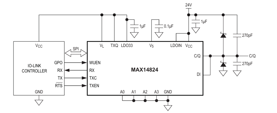
A single IO-Link master port typically consists of a microcontroller, an IO-Link master transceiver, a 24V supply, protective circuitry, and the field connection. In many applications, an M12 connector is used. Here, L+ is usually on pin 1, L- on pin 3, and C/Q on pin 4. Optionally, pin 2 can be used as an additional digital input DI.
The C/Q line is the central line of the IO-Link port. In SIO mode, it is used as a digital switching output or input, and in IO-Link mode, it serves as a bidirectional communication line. The transceiver must be able to actively drive this line, switch it to high impedance, and simultaneously evaluate the line status.
With the MAX14824, this coupling is done via the C/Q pin. Internally, there is a configurable driver with high-side and low-side switches. This allows the component to pull the line towards VCC, pull it towards GND, or use it as an input in a high-impedance state.
Communication with Host
On the microcontroller side, several digital signals are needed. For the actual IO-Link communication, primarily TXC, TXQ, TEXEN and Prescription relevant.
TXC is the Transmit Communication input. This signal typically comes from the microcontroller's UART TX. Serial IO-Link data is passed to the transceiver via this input.
Prescription This is the receiver output of the transceiver. This signal is connected to the microcontroller's UART RX. The transceiver evaluates the level on C/Q and provides a logic signal from it to the microcontroller.
TEXEN activates the C/Q driver. When TXEN is set, the MAX14824 actively drives the C/Q line. When TXEN is deactivated, the driver is turned off and the line can be used for reception. TXEN can, for example, be controlled by an RTS signal from the microcontroller or by a GPIO controlled.
TXQ is another transmit level input. TXQ is logically ANDed internally with TXC. If TXQ is not used separately, the input must be set High. In some designs, TXQ is controlled by a GPIO to distinguish between communication and SIO operation or to generate defined levels on C/Q.
This results in a typical assignment:
Microcontroller UART TX → TXC
Microcontroller UART RX ← RX
GPIO or microcontroller RTS → TXEN
Microcontroller GPIO → TXQ
SPI for microcontroller → CS, SCLK, SDI, SDO
Microcontroller interrupt input ← IRQ
GPIO for Wake-up Control → WUEN
Communication and Switching Operations
The C/Q line is electrically a 24V line, but logically it is the actual IO-Link communication interface. In IO-Link mode, the serial data is transmitted half-duplex via C/Q. The master transmits by activating the transceiver's C/Q driver and switching the line according to the TXC/TXQ signals. After that, the driver is deactivated, and the master receives the device's response via the C/Q receiver.
This switching between sending and receiving is a central concept. That's why TXEN is an important control signal. It prevents the master and device from driving each other simultaneously. In practice, the TXEN signal in firmware must be set and cleared in sync with the UART transmission.
In SIO mode, C/Q can be used as an ordinary digital switching channel. The MAX14824 can be configured as a push-pull, high-side, or low-side driver for this purpose. In push-pull operation, C/Q actively switches between VCC and GND. In high-side operation, the line is switched to VCC, and in low-side operation, it is switched to GND. These operating modes are configured via registers within the device.
Wake-up generation
IO-Link devices are brought into IO-Link communication mode from the SIO state by a wake-up pulse. The MAX14824 has an automatic wake-up polarity generation for this purpose.
The signal Whoa activates this wake-up function. Before wake-up, the C/Q driver is disabled. The component detects the current level on C/Q and then generates a wake-up pulse with the appropriate polarity. The microcontroller does not need to evaluate the polarity of the line itself for this. It activates WUEN and generates a typical 80 µs pulse via TXC or TXQ. The transceiver then converts this into the correct wake-up pulse on the C/Q line.
Für die Hardware bedeutet das: WUEN sollte auf einen steuerbaren GPIO des Mikrocontrollers geführt werden. Die Firmware kann damit gezielt zwischen normalem Kommunikationsbetrieb und Wake-up-Erzeugung umschalten.
Configuration and Diagnostics
In addition to the UART-adjacent signals, the MAX14824 has an SPI interface. Via Computer Science, SCLK, SDI and Social Distortion the module is configured and monitored. The SPI interface operates at up to 12 MHz. Furthermore, the MAX14824 has address pins A0 to A3, allowing up to 16 modules to be used in a system via addressing. This is particularly relevant for multi-channel masters.
Among other things, the C/Q driver mode, slew rate, receiver filter, current sink functions, wake-up mode, and status information are configured via SPI. For COM3, for example, a higher slew rate is used. For lower data rates, the slew rate can be reduced to limit EMC emissions and reflections.
Error conditions are also read out via SPI. These include C/Q faults, undervoltage, temperature warning, and other status bits. The IRQ output can inform the microcontroller when an event has occurred.
Summary
IO-Link enhances traditional sensor and actuator connection technology with digital, bidirectional communication. This ensures low-wiring, high-speed data transmission in a network of IO-Link masters, IO-Link devices, and IO-Link sensors. The technology enables the transfer of process values, diagnostic data, and device parameters over simple standard cables, making the field level more transparent and better integrated into modern automation systems.
This allows IO-Link to achieve communication cycles of less than one millisecond, provided device developers appropriately design the ratio between process data and on-demand data. Therefore, for modern sensors and actuators, IO-Link is an important interface between traditional connection technology and digital automation.