„Does an embedded system have an architecture? Yes, always. Regardless of whether it's “good„ or “bad.„ That's why we start Refactoring and porting projects frequently with a documentation of the embedded systems architecture. It plays a central role in the hardware and software perspective of a technical system. To examine embedded systems architecture descriptions more closely, we must first approach them methodically.
Content
The concept of embedded systems stems from the simple idea of integrating software and hardware systems to create systems with specific properties. Accordingly, their use, applications, and structure play an important role. A breakdown of the termsEmbedded,SystemandArchitectureis therefore indispensable to better categorize embedded systems. The purpose and benefit of the system are crucial.
Key Terms in the Field of Embedded Systems
System
Objectively, a system refers to a collection of many units that follow a set of rules. Thus, one can say that a system is an arrangement of units that help to carry out various types of work according to a fixed plan. For example, a PC operates based on the planned instructions it has been given, and is therefore largely defined by end-user inputs. When you perform a task on the system, you can predict the outcome because all components of the system are interdependent.
Embedded Systems
An embedded system consists of multiple layers of components that can operate specifically according to defined rules. It should be noted that it can either be an independent system determined by the given task, or a part of a more comprehensive system that fulfills the latter's tasks.
In general, the following main components make up embedded systems:
- The fundamental hardware layer: it forms the basis for the other layers of the system;
- the Application Layer – adds the essential software to be processed;
- The OS or platform layer, which defines the rules for the application layer and the interaction between layers. Additionally, monitoring and control routines are stored here.
Embedded systems are typically based on one or more of the elements microprocessor or microcontroller. Additionally, a programmable logic device can be used (FPGA, (CPLD). These control components perform tasks independently within much larger systems. Therefore, they must be extremely reliable throughout the entire process. This is what differentiates embedded systems from, for example, PC-based systems.
Characteristics of Embedded Systems
The task specificity largely determines how the embedded system is developed. Not entirely, but in most all cases, an embedded system is characterized by the following features:
Single-Purpose Orientation: The most common practice for embedded systems is to perform a specific task. Therefore, it repeatedly functions according to the rules set for that particular task.
High time criticality: Processes must be executed very quickly with limited resources. This, in turn, with a severely limited power consumption. Efficiency is a key characteristic of this software-controlled system.
Memory consumption: Controllers and processors have their own ROM memory, which means that a secondary storage is usually not required for the system to operate. However, this memory area generally does not exceed single-digit gigabyte ranges and is therefore significantly smaller than conventional hard drives and flash memory.
Consistency and Reliability: Microcontroller and microprocessor-based systems are extremely reliable, efficient, and stable in their operation. However, unlike in home electronics and PC applications, lifespans and uptimes of several years are not uncommon.
Interfaces: To enable a connection to peripherals, such as sensors or actuators, as well as components of the super-system, connections to the outside world of the system must be present. These connections are rarely standardized and in most cases depend on the manufacturer.
Describe architectures
The architecture description finally summarizes the first solution layer and thus forms the basis for implementing the embedded system as a PCB layout on the one hand and as software on the other. The architecture description is therefore the most important element for implementing the first implementation layer, where requirements are translated into concrete design decisions. With embedded systems, a distinction is typically made between hardware and software views, which together form a complete picture. A holistic view that can represent all aspects – temporal, dynamic, and structural – simultaneously is not desirable.
Reviewing the hardware architecture
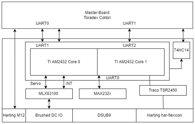
Block diagram
The classic among hardware architectures. rough PCB layout is defined here. Initial decisions are made regarding component selection and pin assignments. The important thing here is to focus on central components and to prioritize the technical solution.
Bill of Materials as preliminary parts selection
A bill of materials in list form is essential for further determining the engineering development focus. Here, the components are specified in a table so that they can be procured. Tools such as Octopart's BOM Tool (https://octopart.com/bom-tool) serve to avoid obsolescence traps at this point and provide an initial cost indication via distributor prices. It is important to focus on functional or difficult-to-source parts. Standard components such as ferrites, resistors, capacitors, inductors, fuses, or LDOs should be left out.
Power Domain Management
As a special case in the area of embedded systems hardware architecture, but with particular attention. Power domain management serves to assign central building blocks on the PCB hardware to individual power domains. An exemplary power domain diagram is shown below and designs the power supply for input and output variables of a PMIC-driven microprocessor.
Reviewing the Software Architecture
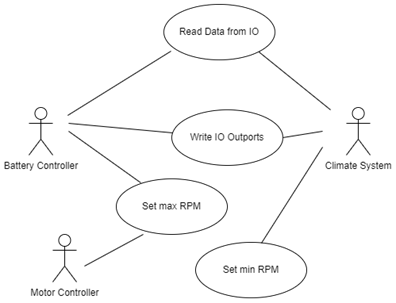
Feature diagram or Use case diagram
The first view in the functional software context is the customer view. This serves, particularly at the planning and organizational level, as an initial foundation for what the system is actually supposed to deliver to the customer. A use case specification thus helps to break down the software into functional blocks in the first instance and to deliver individual overarching domains.
Dynamic View IProcess Diagram: The process diagram is not used here for functional definition, but for a general purpose of the software. Following the input-process-output (EVA) principle, it is suitable to determine which data is input per cycle in order to generate output data within a functional context.
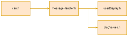
Dynamic View II – Dataflow Diagram
The data flow diagram essentially describes the interrelationships between modular constructs that are typically combined in a source file. It is sufficient at this point to show how specific components interact with each other within the scope of a specific task. A view that anticipates the solution is not yet necessary at this point.
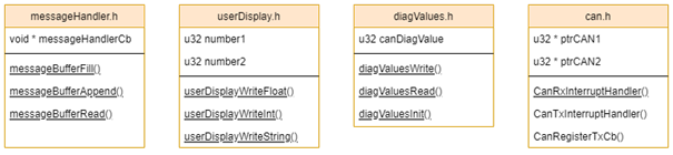
Static View – Component and Interface Architecture
The static view follows the dynamic view – not the other way around. Once the dynamic cohesion of the system has been established, the transition to the static view can occur. This is the first approach to design-oriented implementation and therefore takes precedence when building the source code. A developer will thus likely read this part first, as central requirements for the intended tree or layer structure of the source files are stored here. The component and interface architecture summarizes requirements for functions, members, memory, classes, and typedefs.
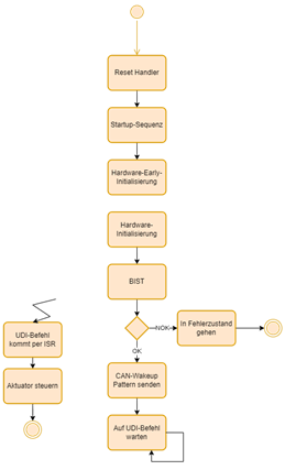
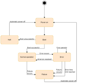
State ViewThe state view is an essential conceptual approach for explaining what an embedded system is prepared to deliver under which conditions. This means that certain cycles may only be traversed by software if, for example, external boundary and framework conditions are not exceeded or undershot by sensor and input values. For the definition of safety-critical systems, this part is therefore one of the most important, because it must take error states and critical transitions into account.
Cross-sectional concepts
Finally, general structures and aspects that apply system-wide are listed. In the context of embedded systems, these can also include IDEs or compilers. For example, if a uniform task system is to be used or a special memory concept, this will be mentioned at this point. The description is textual here. The choice of the respective concepts must be justified.
Scope and Cataloging
The architectural description of an embedded system is typically very comprehensive and should not be misunderstood as a rough sketch. Rather, it functions as a structured catalog of all relevant system aspects. Every single feature must be represented in it – regardless of whether it is a central main function or a seemingly trivial detail. The term "feature" should be understood broadly and can be broken down to a very fine-grained level, such as individual communication paths, state transitions, timing requirements, or specific hardware dependencies. This granularity is necessary to ensure complete traceability between requirements, architecture, and implementation. Accordingly, the cataloging is usually done systematically along views, modules, or domains, so that both functional and non-functional properties can be clearly assigned, referenced, and later verified.
Summary
The description and definition of architectures do not follow a standard work but are an interplay of various perspectives and viewpoints. Especially in the highly regulated context of industrial embedded systems, a structured and methodologically sound approach is therefore necessary, which contrasts the central questions from the requirements specification with an initial implementation idea.